Q. What is Difference between MIB and SIB?
MIB and SIB are two types of System Information (SI) that is broadcasted in the serving are of particular cell. SI is carried by the logical channel BCCH, which in turn is carried by either of the transport channels BCH or DL-SCH.
Master information Block (MIB): is a static part of SI and contain information like number of antennas, system bandwidth,PHICH configuration, transmitted power and scheduling information on how the SIBs are scheduled together with other data on DL-SCH. MIB is transmitted on the BBCH–> PBCH with
periodicity of every 40 ms.
System Information Block (SIB): is a dynamic part of SI. It carries relevant information for the UE, which helps UE to access a cell, perform cell re-selection, information related to INTRA-frequency, INTER-frequency and INTER-RAT cell selections. It is mapped on DL-SCH –>PDSCH with periodicity of every 80 ms, 160ms or 320ms for SIB1,SIB2 and SIB3 respectively.
Q. How many types of SIBs are available in LTE?
There are 13 types of SIBs for LTE.
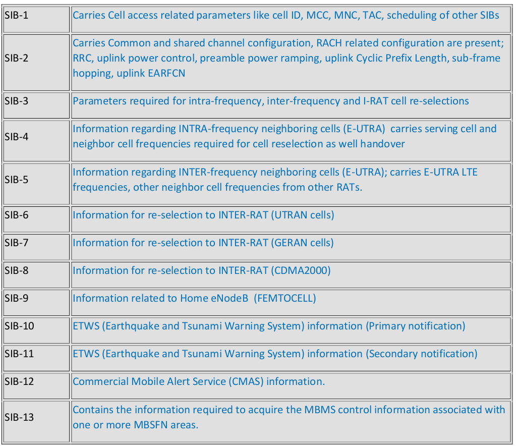
Q. What does SIB1/SIB2/ … /SIB13 do?
Each SIB carry information related to specific tasks.
Q. On which channels SIBs are transmitted?
BCCH–> DL-SCH–> PDSCH.
Q. Which SIBs are essential?
In LTE, for a UE to access the eNB, at the most minimum 2 SIBs are required (SIB1 and SIB2). Information regarding SIB2-SIB13 are carried in SI messages and are included in scheduling Info List which is part of SIB1.
Q. Why we need SIB19?
SIB 19 is needed when UE is coming back from 3G to 4G. LTE priority should be set high in 3G. SIB19 carries the absolute priority of the serving UMTS cell, the absolute priorities of the LTE frequencies, and the cell reselection thresholds.
Q. How can we calculate LTE DL/UL throughput?
Lets’ assume we have 20 MHz channel bandwidth.
we need to calculate the resource elements in a sub frame for this band i.e.
12 subcarriers x 7 OFDMA symbols x 100 resource blocks x 2 slots= 16800 REs per subframe.
Assume we have 64 QAM modulation and no coding, one modulation symbol will carry 6 bits.
16800 modulation symbols x 6 bits / modulation symbol = 100800 bits.
So, the data rate is 100800 bits / 1 ms = 100.8 Mbps.
With 4×4 MIMO, the peak data rate goes up to 100.8 Mbps x 4 = 403 Mbps.
Estimate about 25% overhead e.g. PDCCH, reference signal, sync signals, PBCH, and some We get 403 Mbps x 0.75 = 302 Mbps.
Q. What is SON & how does it work in LTE?
Self-configuring, self-optimizing wireless networks is not a new concept but as the mobile networks are evolving towards 4G LTE networks, introduction of self-configuring and self-optimizing mechanisms is needed to minimize operational efforts. A self-optimizing function would increase network performance and quality reacting to dynamic processes in the network. This would minimize the life cycle cost of running a network by eliminating manual configuration of equipment at the time of deployment, right through to dynamically optimizing radio network performance during operation.
Ultimately it will reduce the unit cost and retail price of wireless data services. See Self-configuring and self-optimizing Networks in LTE for details.
Q. How does Timing Advance (TA) works in LTE?
In LTE, when UE wish to establish RRC connection with eNB, it transmits a Random Access Preamble, eNB estimates the transmission timing of the terminal based on this. Now eNB transmits a Random Access Response which consists of timing advance command, based on that UE adjusts the terminal transmit timing. The timing advance is initiated from E-UTRAN with MAC message that implies and adjustment of the timing advance. See Timing Advance (TA) in LTE for further details.
Q. How does LTE UE positioning works in E-UTRAN?
UE Positioning function is required to provide the mechanisms to support or assist the calculation of the geographical position of a UE. UE position knowledge can be used, for example, in support of Radio Resource Management functions, as well as location-based services for operators,
subscribers, and third-party service providers. See LTE UE positioning in E-UTRAN for more details.
Q. How does Location Service (LCS) work in LTE network?
In the LCS architecture, an Evolved SMLC is directly attached to the MME. The objectives of this evolution is to support location of an IMS emergency call, avoid impacts to a location session due to an inter-eNodeB handover, make use of an Evolved and support Mobile originated location request (MO-LR) and mobile terminated location request MT-LR services. Release 9 LCS solution introduces new interfaces in the EPC:
SLg between the GMLC and the MME
SLs between the E-SMLC and the MME
Diameter-based SLh between the HSS and the HGMLC
Q. How does Lawful Interception work in LTE Evolved Packet System?
3GPP Evolved Packet System (EPS) provides IP based services. Hence, EPS is responsible only for IP layer interception of Content of Communication (CC) data. In addition to CC data, the Lawful Interception (LI) solution for EPS offers generation of Intercept Related Information (IRI) records from respective control plane (signaling) messages as well. See Lawful Interception Architecture for LTE Evolved Packet System for more details.
Q. What is carrier aggregation in LTE-Advanced?
To meet LTE-Advanced requirements, support of wider transmission bandwidths is required than the 20 MHz bandwidth specified in 3GPP Release 8/9. The preferred solution to this is carrier aggregation. It is of the most distinct features of 4G LTE-Advanced. Carrier aggregation allows expansion
of effective bandwidth delivered to a user terminal through concurrent utilization of radio resources across multiple carriers. Multiple component carriers are aggregated to form a larger overall transmission bandwidth.
Q. What is LTE Intra E-UTRAN Handover?
Intra E-UTRAN Handover is used to hand over a UE from a source eNodeB to a target eNode Busing X2 when the MME is unchanged. In the scenario described here Serving GW is also unchanged. The presence of IP connectivity between the Serving GW and the source eNodeB, as well as between the Serving GW and the target eNodeB is assumed. The intra E-UTRAN HO in RRC_CONNECTED state is UE assisted NW controlled HO, with HO preparation signaling in E-UTRAN. To prepare the HO, the source eNB passes all necessary information to the target eNB (e.g. E-RAB attributes and RRC context) and UE accesses the target cell via RACH following contention-free procedure using a dedicated RACH preamble. The HO procedure is performed without EPC involvement, i.e. preparation messages are directly exchanged between the eNBs.
Q. What RBS Hardware does Ericsson use for LTE Technology?
RBS 6000 series
Q. What is considered a good RSRP and RSRQ threshold, good for LTE radio conditions?
RSRP = >-95 dBm (Planning with -113 dBm)
RSRQ=<-7db
Q. What latency (RTT) have you experienced while pinging with 32 bytes?
40-200ms
Q. What technology is used in the uplink and in the downlink?
Uplink: SCFDMA
Downlink: OFDMA