Principles of 8T8R Beamforming
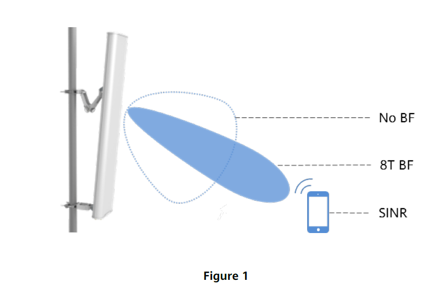
Beamforming is a digital signal processing technology that can be implemented on adaptive 8T8R array antennas. Baseband weighting of multiple antennas transmitting signals is used to form high-gain, narrow beams. These beams target user devices, improving signal strength and reducing interference, as shown in the figure 1 below.
8T8R Antenna Introduction
Smart 8T8R antennas adopt multiple-antenna 8-array technology. In combination with adaptive algorithms executed in the RAN base station equipment, these antennas can achieve good beamforming performance.
Figure 2 below shows a typical 8T8R antenna. Four dual-polarized antenna columns correspond to 8 RF ports and 1 calibration port.
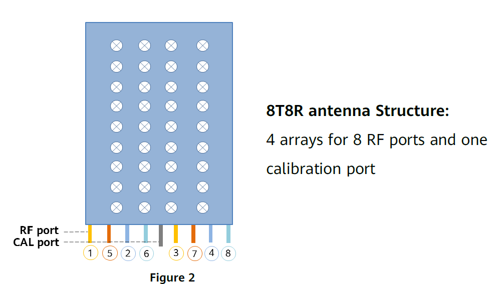
The eight RF ports on the antenna are connected to eight individual RF channels. Each RF channel uses the corresponding single column beam to radiate energy.
In order to achieve high accuracy of the weighted signals at the antenna connection points, which is necessary to ensure the desired radiation patterns, calibration is required. Even though the weighted signals are accurately provided by the baseband- and RF equipment connected to the antenna, changes to the signal at the antenna connection ports can be caused by the cabling between radio and antenna. In order to remove any influence from the cabling, calibration is performed through a dedicated calibration port. The amplitude and phase of the signal at each of the eight RF ports is continuously calibrated, removing RF signal differences caused by the cables connecting the antenna with the radio equipment. This enables beam forming with consistently high accuracy.
Currently, there are two main types of TDD 8T8R antenna. Take Huawei antennas as an example.

8T8R Antenna Beams Introduction
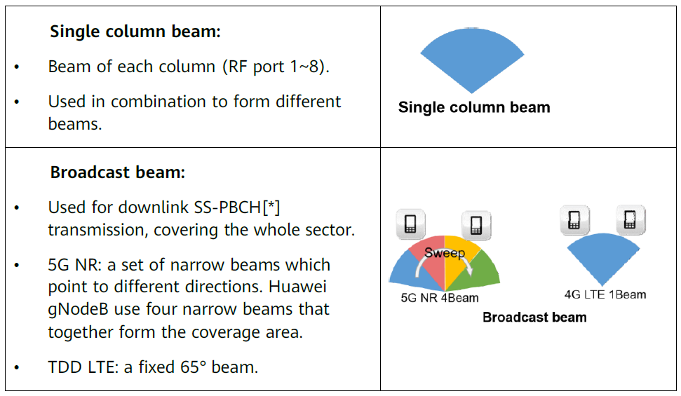
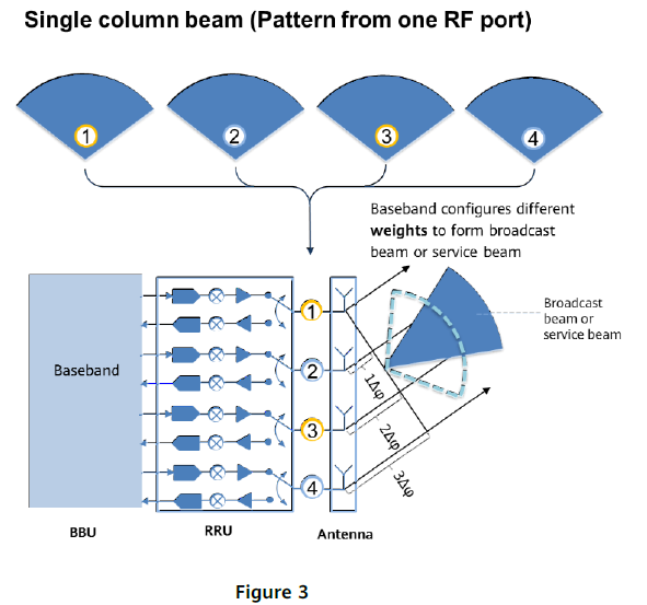
Single column beam: Each RF channel uses the corresponding single column beam to radiate energy. Baseband weighting is used to configure different changes to the amplitude and phase for each of the RF ports, in order to form broadcast and service beams of specific patterns and directions. Unweighted single columns are typically used for uplink receive channels.
Beamforming for broadcast channels: Fixed-weight beamforming is used to process the broadcast channel, control channel, and reference signals of all user devices in a cell. Different fixed antenna weights (amplitude and phase) can be configured to change the coverage scope of the broadcast beams, improving cell coverage performance.
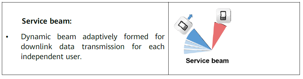
Beamforming for service channels: PDSCH dynamic adaptive beamforming is used for user devices. Narrow beams are formed in order to concentrate energy on target user devices and reduce interference to surrounding user devices. The beamforming is based on TDD uplink and downlink channel reciprocity and uplink channel measurements. This increases the demodulation SINR for target user devices and improves cell-edge performance.
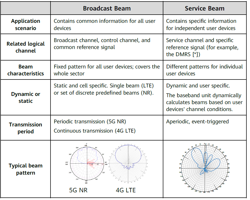
Difference between Broadcast and Service Beams
Broadcast beams determine the coverage area. 5G NR broadcast beams are different from 4G LTE broadcast beams: 5G NR uses four discrete fixed narrow beams periodically scanning data transmission, while 4G LTE uses one fixed 65° beam continuously transmitting data. Service beams are used for data transmission.
How Beams are Formed
Each RF channel uses the corresponding single column beam to radiate energy. 8T8R beamforming in the baseband configures different RF channel weights, consisting of changes to amplitude and phase of the signals for each of the eight RF ports. The resulting radiation of the combined weighted antenna columns forms broadcast- and service beams of specific patterns and directions, as illustrated in figure 3 below.
Weight Configuration
As described above, 8T8R antenna signal weighting can be applied across the RF ports. By using different weighting factors, the antenna radiation characteristics such as coverage of broadcast- and service beams can be changed.
Broadcast Beam Weight Configuration
Usually RAN equipment suppliers use BBU and OMC (operation and maintenance center) to get and configure broadcast beam weights. Some suppliers have other options to manage weighting factors. For example, Huawei eNodeB (TDD LTE) also supports a RAE (Remote Antenna Extension) based solution for configuring broadcast beam weights.
The first solution is that default broadcast beam weights are written into the BBU by itself and will be activated when configuring 8T8R beamforming.
The second solution is that antenna weighting factors are imported to OMC of the base station. BBU will activate the weight information delivered from OMC.
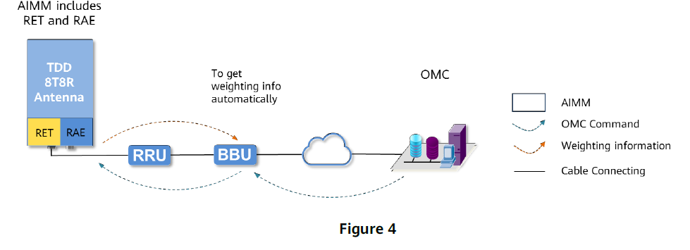
The third solution is usually used in some particular scenarios in TDD LTE 8T8R, like forming the beam from 65°beam width to 33°beam width for highway coverage. This solution is a cooperative solution of RAN and antenna: A RAE device is used to store antenna weight information in an antenna, available from factory delivery. Then BBU automatically reads and configures the weighting factors stored in the RAE device. The data transfer is performed according to the AISG protocol, as shown in figure 4 below.
Huawei 5G NR RAN currently supports to configure weights in BBU, and is expected to support other solutions in future.
Service Beam Weight Configuration
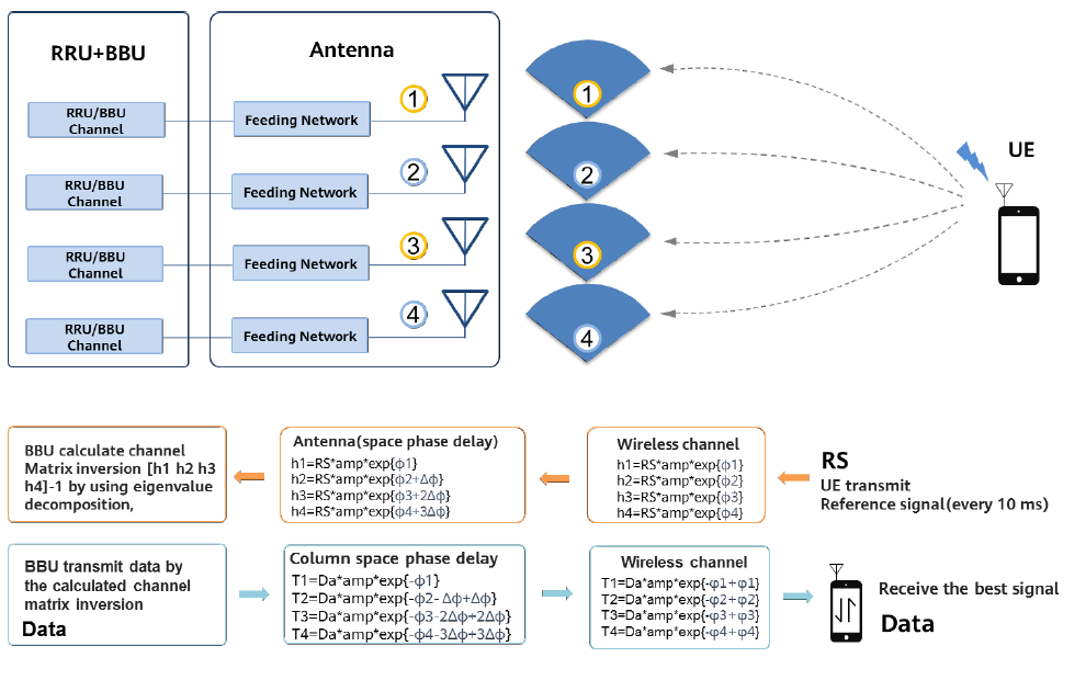
Because of TDD uplink and downlink radio channel reciprocity, base stations can calculate the downlink service channel weights through the uplink channel as follows:
Step 1: The user device transmits sounding reference signals (SRS) in an uplink channel. The uplink SRS is a standard reference signal specified in 3GPP specifications and can be identified by base station receivers.
Step 2: All of the base station’s receive channels simultaneously receive the SRS. The radio propagation channel and antenna array alter the amplitude and phase of the signal obtained by each receive channel. Based on these received signals, the base station estimates and calculates each received SRS. Through this, the amplitude and phase changes caused by the radio propagation channel and the antenna array corresponding to each channel for the signal is obtained.
Step 3: The amplitude and phase of each channel are adjusted using the weights for each channel’s downlink data. When all channels simultaneously transmit the data that has been adjusted using the respective weights, based on TDD channels’ uplink and downlink reciprocity, the radio propagation channels and the antenna arrays alter the amplitude and phase of the downlink signals. Those alterations are the same as in the uplink. Therefore, the combined signal resulting from those individually transmitted signals, received by the user equipment, is optimized for signal strength and interference. Figure 5 below illustrates this principle.
Source: Huawei.com