The purpose of using an antenna array, as shown in Figure 7.1-A, is to enable high gain beams and the ability to steer those beams over a range of angles. The gain is achieved, in both UL and DL, by constructively combining signals from a number of antenna elements. The more antenna elements utilized, the higher the antenna gain in general. The steerability is achieved by individually controlling the amplitude and phase of smaller parts of the antenna array. This is usually done by dividing the antenna array into so-called subarrays (groups of non-overlapping elements), as shown in Figure 7.1-C, and by applying two dedicated radio chains per subarray (one per polarization) to enable control, see Figure 7.1-D. In this way, the direction and other radiation characteristics of the antenna array beam is controlled.

Notes: A typical antenna array (A) is made up of rows and columns of individual dual-polarized antenna elements (B). Antenna arrays can be divided into subarrays (C), with each subarray (D) connected to two radio chains, normally one per polarization.
To see how an antenna array creates steerable high-gain beams, we start with an antenna array of a specific size, which is then divided into subarrays of different sizes. For illustrative purposes, we describe only one dimension. The same principles do, however, apply to both vertical and horizontal dimensions of the antenna.
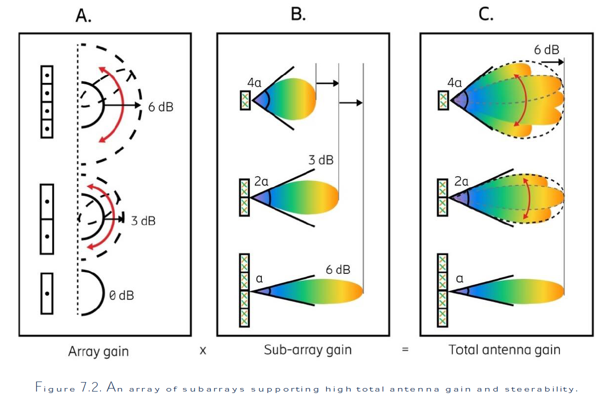
The array gain is referred to as the gain achieved when all subarray signals are added constructively (in phase). The size of the array gain relative to the gain of one subarray depends on the number of subarrays. For example, two subarrays give an array gain of 2 (therefore, 3 dB). By changing the phases of the subarray signals in a certain way, this gain can be achieved in any direction as shown in Figure 7.2-A.
Each subarray has a certain radiation pattern describing the gain in different directions. The gain and beam width depend on the size of the subarray and the properties of the individual antenna elements. There is a trade-off between subarray gain and beam width – the larger the subarray, the higher the gain and the narrower the beam width, as illustrated in Figure 7.2-B
The total antenna gain is the product of the array gain and the subarray gain, as shown in Figure 7.2-C. The total number of elements determines the maximum gain and the subarray partitioning allows steering of high gain beams over the range of angles. Moreover, the subarray radiation pattern determines the envelope of the narrow beams (the dashed shape in Figure 7.2-C. This has an implication on how to choose antenna array structure in a real deployment scenario with specific coverage requirements.
Since each subarray is normally connected to two radio chains, one per polarization, and each radio chain is associated with a cost in terms of additional components. It is important to consider the performance benefits of additional steerability when choosing a cost-efficient array structure.
Source: Advanced Antenna Systems for 5G by 5G Americas (White paper)