Binary Frequency Shift Keying (BFSK) is a type of digital modulation technique in which we are sending one bit per symbol i.e., ‘0’ or a ‘1’. Hence, the bit rate and symbol rate are the same. In BFSK, the information is encoded in the variation of the frequency of the carrier. We represent ‘0’ by carrier frequency ‘

For example, we can have the following transmitted band-pass symbols:


Where ‘E’ is the symbol energy, ‘T’ is the symbol time period. Using Gram-schmidt orthogonalization, we get a two orthonormal basis function for 


As these two basis functions are orthogonal to one another, hence, the resulting constellation diagram can be given as:
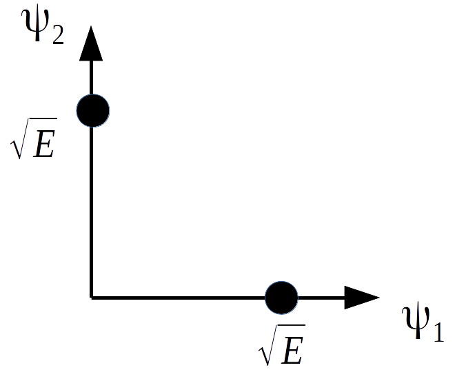
There is an in-phase components and a quadrature component.
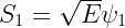
Hence we can write symbols 


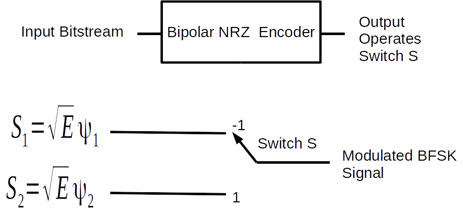
The BFSK Modulator
A simple BFSK modulator is shown in figure below. The incoming bit sequence is first encoded by a bipolar NRZ encoder. The NRZ encoder converts these digital bits into impulses to add a notion of time into them. Then NRZ waveform is generated by up-sampling these impulses. Afterwards, the output of NRZ encoder operates a switch. Based on whether the encoder’s output is +ve or -ve, the switch sends symbol
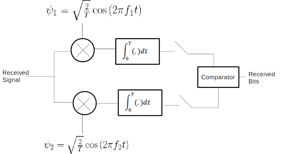
Demodulator Design:
Here, we do coherent demodulation of the BFSK signal at the receiver. Coherent demodulation requires the received signal to be multiplied with the carrier having the same frequency and phase as at the transmitter. The phase synchronization is normally achieved using Phase Locked Loop (PLL) at the receiver. PLL implementation is not done here, rather we assume perfect phase synchronization.
Block diagram of BFSK modulator is shown in the figure below.
The incoming BFSK signal is multiplied with two locally generated carriers, i.e., 

The Matlab simulation code is given below. Here for the sake of simplicity, the bit rate is fixed to 1 bit/s (i.e., T=1 second). It is also assumed that Phased Locked Loop (PLL) has already achieved exact phase synchronization.
clear all;
close all;
%Bits to be transmitted
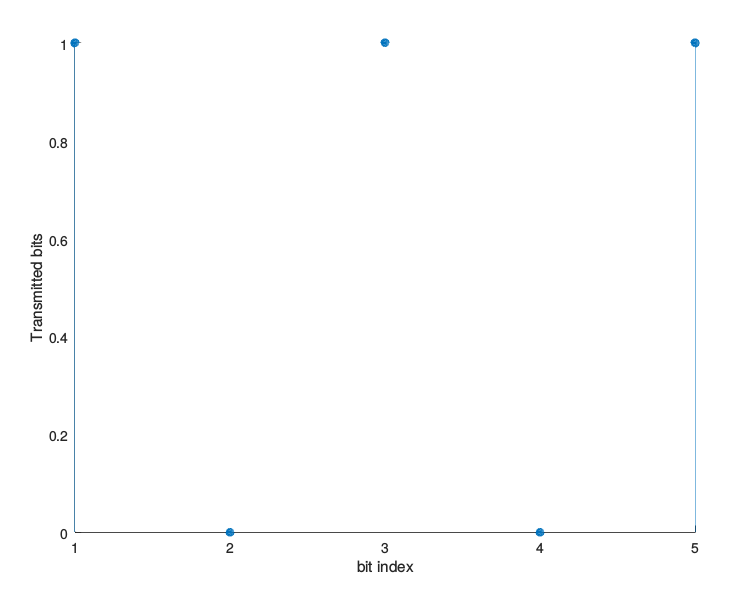
b=[1 0 1 0 1]
%Rb is the bit rate in bits/second
NRZ_out=[];
%Vp is the peak voltage of Bipolar NRZ waveform
Vp=1;
%Here we encode input bitstream as Bipolar NRZ-L waveform
for index=1:size(b,2)
if b(index)==1
NRZ_out=[NRZ_out ones(1,200)*Vp];
elseif b(index)==0
NRZ_out=[NRZ_out zeros(1,200)*(-Vp)];
end
end
%figure(1);
%stem(b);
%figure(2);
plot(NRZ_out);
t=0.005:0.005:5;
f1=3;
f2=5;
A=5; %It is the square root of symbol energy
%Depending on whether the output of NRZ encoder is positive or negative
%we switch between the two BFSK symbols to generate modulated signal
modulated=[];
for (i=1:1:length(NRZ_out))
if (NRZ_out(i)==1)
y=A*cos(2*pi*f1*t(i));
else
y=A*cos(2*pi*f2*t(i));
end
modulated=[modulated y];
end
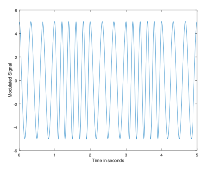
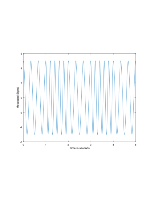
%Plot the modulated signal
plot(t,modulated)
xlabel('Time in seconds')
ylabel('Modulated Signal')
%Demodulation starts here
%Multiply the received signal with psi 1 in branch 1
demodulated_branch_1=modulated.*(cos(2*pi*f1*t));
%Multiply the received signal with psi 2 in branch 2
demodulated_branch_2=modulated.*(cos(2*pi*f2*t));
%Here we perform the integration over time period T in the two
%branches using trapz,
%Integrator is an important part of correlator receiver used here
y_1=[];
for i=1:200:size(demodulated_branch_1,2)
y_1=[y_1 trapz(t(i:i+199),demodulated_branch_1(i:i+199))];
end
y_2=[];
for i=1:200:size(demodulated_branch_2,2)
y_2=[y_2 trapz(t(i:i+199),demodulated_branch_2(i:i+199))];
end
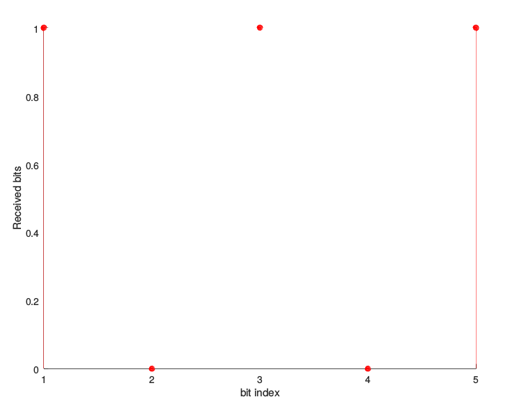
% Compare the output of two branches to decide if a 1
% or 0 was transmitted
received=y_1>y_2;
figure;
stem(b, 'filled')
xlabel('bit index')
ylabel ('Transmitted bits')
figure;
stem(received, 'filled', 'r' )
xlabel(' bit index ' )
ylabel(' Received bits ' )
<pre>
One response to “Binary Frequency Shift Keying (BFSK) Modulation And Demodulation-Matlab Code With Explanation”
please explain it brefily advantage of bfsk , modulator demodulator with help of diagram